
Connectors and Pinouts
The pictures on this page are renders of the circuit boards, seen from the back of the DMX Core 100. The orange labels name each pin; the white text printed on the board (silkscreen) says the same thing, so you can check it on the unit.
DC power input
If you don’t use Power over Ethernet, power the DMX Core 100 from an 8–28 VDC supply (not included) on the green 2-pin terminal next to the corner of the main board. It is a pluggable terminal block with 3.5 mm pitch, and the plug is included: strip the wires, screw them into the plug, and push the plug onto the header.
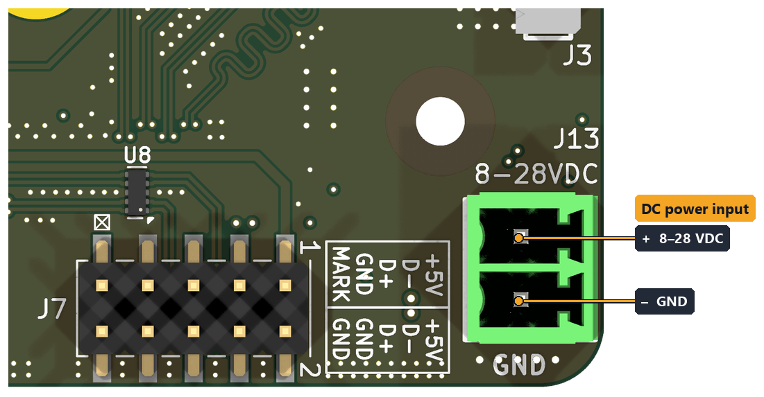
| Pin | Board marking | Connect to |
|---|---|---|
| Upper pin | 8-28VDC | Supply + (positive) |
| Lower pin | GND | Supply – (negative / ground) |
- The unit draws at most 8 W (about 0.5 A at 12 VDC). A 12 V or 24 V adapter rated 1 A or more leaves plenty of headroom.
- For a wall adapter with a barrel plug, use a DC barrel-jack-to-screw-terminal adapter (pigtail) and wire its + and – to the plug as shown. Check the polarity with a meter before connecting; a center-positive adapter is not always marked.
- You can connect PoE and DC at the same time for redundancy. The unit runs from one of them and switches over automatically if that one is lost.
- There is no power switch: the unit starts when power is applied. See Installation.
DMX pinout and XLR
All the DMX ports on the expansion boards use the same three signals. To wire one to an XLR connector:
| Board pin | Signal | XLR pin |
|---|---|---|
A | Data + | 3 |
B | Data – | 2 |
COM / GND | Common (shield) | 1 |
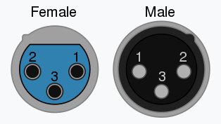
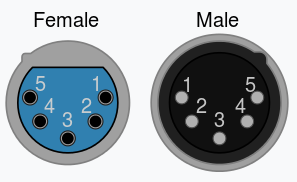
On a 5-pin XLR, pins 4 and 5 (the optional second data pair) are not used.
2-port DMX-512 board
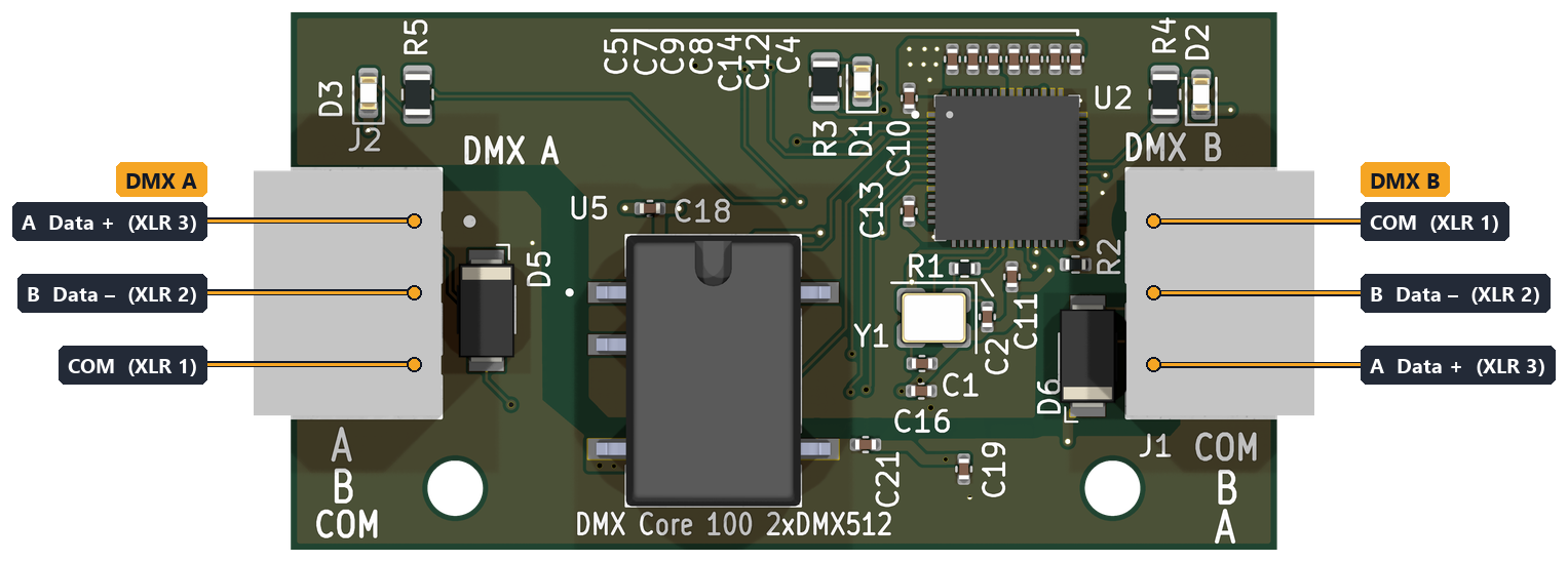
Two isolated DMX-512 ports, DMX A on the left and DMX B on the right. Each can be an input or an output; see Passthrough and Stream Routing. Note that the two terminals are mirror images: on DMX A the A pin is at the top, on DMX B it is at the bottom.
| Terminal | Pin (top to bottom) | XLR pin |
|---|---|---|
| DMX A | A Data + / B Data – / COM | 3 / 2 / 1 |
| DMX B | COM / B Data – / A Data + | 1 / 2 / 3 |
Audio board
Stereo line outputs, available balanced and unbalanced at the same time.
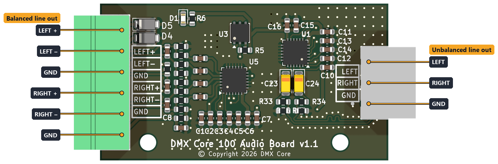
Balanced line out (6-pin, left), top to bottom:
| Pin | Signal | XLR pin |
|---|---|---|
| 1 | LEFT + | 2 |
| 2 | LEFT – | 3 |
| 3 | GND | 1 (shield) |
| 4 | RIGHT + | 2 |
| 5 | RIGHT – | 3 |
| 6 | GND | 1 (shield) |
Unbalanced line out (3-pin, right), top to bottom: LEFT, RIGHT, GND.
- Use the balanced outputs for any cable that leaves the enclosure, into a balanced (differential) input. Connect
GNDto the cable shield only; don’t use it as a signal return. - Use the unbalanced output for short runs to equipment in the same rack or enclosure.
- The audio outputs are not isolated. If the connected amplifier puts DC on the line or there is a ground loop (hum), put a DI box or line isolation transformer in between.
ADIO board
Audio outputs (same as the audio board), two isolated DMX-512 ports and four digital inputs.
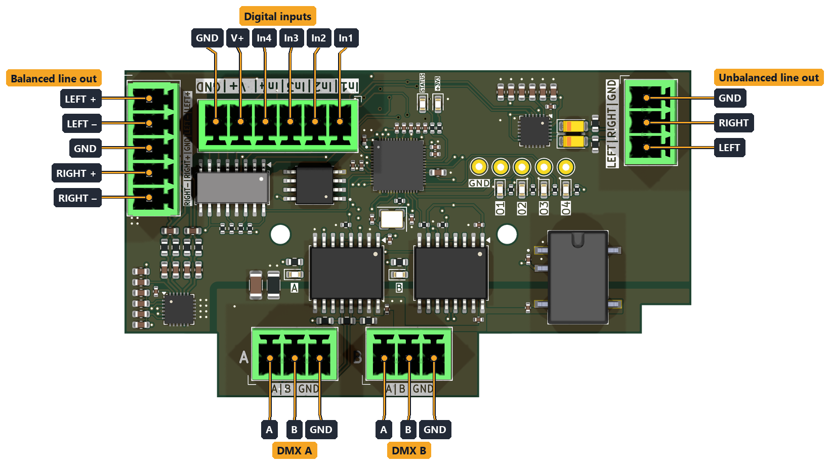
DMX A and DMX B (3-pin, bottom), left to right: A Data + (XLR 3), B Data – (XLR 2), GND (XLR 1). See DMX pinout and XLR.
Balanced line out (5-pin, left), top to bottom: LEFT +, LEFT –, GND, RIGHT +, RIGHT –. On an XLR: + to pin 2, – to pin 3, GND to pin 1.
Unbalanced line out (3-pin, right), top to bottom: GND, RIGHT, LEFT.
Digital inputs (6-pin, top), right to left: In1, In2, In3, In4, V+, GND. Older boards mark V+ as 3V3; it is the same pin.
| Pin | Function |
|---|---|
In1–In4 | Trigger inputs 1–4 (opto-isolated, about 3–30 VDC, about 5 mA) |
V+ | Contact-wetting supply: the voltage that drives an input through a dry contact (switch, push button, relay contact) |
GND | Input common |
- Dry contact or push button: wire the switch between
V+and an input. - Voltage signal or PLC output: connect the signal + to an input and its 0 V / return to
GND, and leaveV+unconnected.
The inputs, V+ and GND are isolated from the rest of the DMX Core 100, together with the ADIO board’s DMX ports. On early ADIO boards (marked v1.0 on the underside, the side facing the main unit) they are not: there, dry contacts on V+ (marked 3V3) only work with jumper J5 fitted, which ties the input GND to the unit’s ground.
An input is active while voltage is applied, so a closed switch is active. Use the inputs with Digital Input triggers.
The four O1–O4 pads on the ADIO board are indicator LEDs for the Digital Output events, not a field connector.