
Wiring
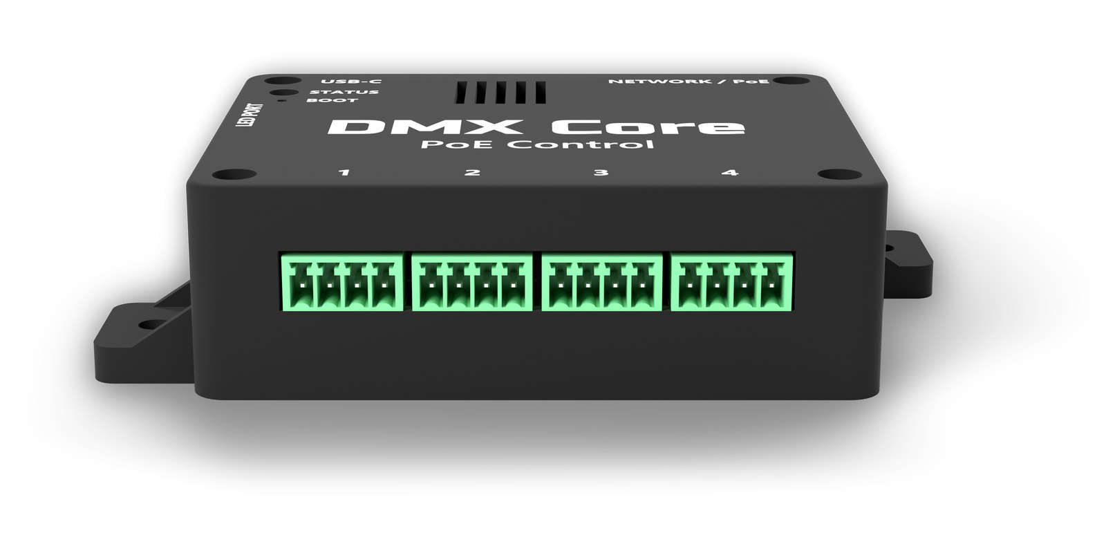
Control ports
Four ports, each a 4-pole pluggable 3.5 mm screw terminal. A plug for each is in the box. The legend on the enclosure gives the port number and the pin names:
| Pin | Name | Encoder | Buttons |
|---|---|---|---|
| 1 | A | encoder A (CLK) | button 1 |
| 2 | B | encoder B (DT) | button 2 |
| 3 | S | push switch | button 3 |
| 4 | GND | encoder common and switch common | button common |
Every input is a contact closure to GND. The controller supplies the pull-ups, so the field wiring is passive switches only, and there is deliberately no power pin on the ports: a bare encoder or a button needs none, and a supply on a screw terminal is one slipped screwdriver away from a short. Behind each pin is a series resistor, a noise filter and an ESD clamp to the rails, so the port survives a hand on the terminals and a wire brushed onto 12 V.
In config.txt a port is named by its GPIO numbers:
| Port | Knob pins | Button pin choices |
|---|---|---|
| 1 | 2,3,4 | 2, 3, 4 |
| 2 | 5,6,7 | 5, 6, 7 |
| 3 | 8,9,10 | 8, 9, 10 |
| 4 | 11,12,13 | 11, 12, 13 |
Rotary Encoder Kit
The ready-made knob, sold separately for the DMX Core PoE Control, one kit per knob: a Bourns PEC11R rotary encoder with push switch on a 19 x 31 mm panel board, an aluminum knob, and a 200 mm cable with a JST XH plug at the board end and four ferrules at the other.
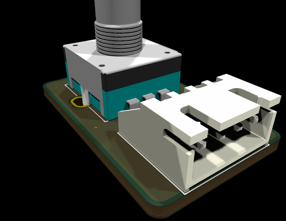
Mounting. Drill a hole for the encoder’s M7 threaded bush in the panel, push the board through from behind, and tighten the nut. The nut is all that holds it - the board needs no screws. Push the knob onto the splined shaft.
Connecting. Plug the cable into the board’s header, then put the four ferrules into a control-port plug in order:
| Cable color | Signal | Port pin |
|---|---|---|
| brown | A | 1 |
| white | B | 2 |
| black | S | 3 |
| blue | GND | 4 |
It is wired straight through, so the conductor at cable position 1 goes to port pin 1, and so on. Do not tin the ferrule end; the ferrule is the termination.
24 detents per revolution, one step per click. The firmware expects an encoder that makes one full quadrature cycle per detent, which this one does.
Cable length
Up to about 10 m of ordinary multi-core cable per port is fine. Beyond a couple of meters, or next to dimmer or mains cabling, use a twisted pair per signal with its GND, or shielded cable with the shield on the port’s GND at the controller end only.
The encoder kit’s cable is 200 mm; standard JST XH 4-pin extension cables (sold as 3S LiPo balance lead extensions) lengthen it between the cable and the encoder board.
Your own encoder
Any standard quadrature rotary encoder works - EC11 and PEC11 types, and KY-040-style modules:
- A goes to pin 1, B to pin 2, the common to GND, the push switch between S and GND. Swapping A and B only reverses the direction, which
invert = 1inconfig.txtputs right. - Use an encoder with one full quadrature cycle per detent (pulses per revolution equal to detents per revolution, as on the Bourns PEC11R-4220). A half-step encoder (pulses equal to half the detents) registers a step every other click.
- A KY-040 module has its own pull-ups and a
+pin. Leave+unconnected; the module works from the port’s pull-ups alone. - No capacitors are needed. The encoder is decoded by counting every transition, so contact bounce cancels itself out.
Buttons
Any momentary push button, normally open, between one of the port’s three lines and GND. Up to three buttons per port, each its own [button] section in config.txt with the line’s GPIO as its pin. Buttons are debounced in firmware (20 ms).
A port is either one encoder or up to three buttons. Across the four ports that is any mix - two knobs and six buttons, or one knob and nine buttons.
Panel LED port
A 3-pole terminal on the side of the box, apart from the control ports so the plugs cannot be swapped by mistake, continues the on-board status LED’s chain out to addressable RGB LEDs mounted in the panel with the knobs. Wiring any is optional.
| Pin | Name |
|---|---|
| 1 | 5V (fused) |
| 2 | DATA |
| 3 | GND |
LEDs. WS2812-compatible parts, up to 8 in a chain. The classic 5 mm through-hole shape - Worldsemi WS2812D-F5 or the PL9823-F5 - pushes into an ordinary 5 mm panel bezel or LED clip and has four legs: DIN, 5V, GND, DOUT. Wire 5V and GND to every LED, DATA from the port to the first LED’s DIN, then each LED’s DOUT to the next one’s DIN. Solder a 100 nF capacitor across 5V and GND at each LED’s legs; through-hole WS2812 parts have no built-in one. Keep the run to the first LED under about 3 m.
The controller caps the chain’s total current at 80 mA, plenty behind a panel, whatever led_brightness says. What the panel LEDs show follows the status LED today; per-button and per-knob feedback is planned.
Power
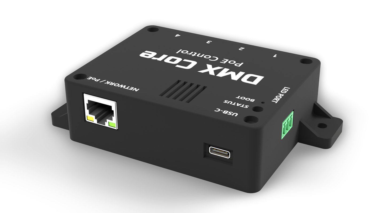
PoE from any IEEE 802.3af or 802.3at switch or injector, on either the data pairs or the spare pairs. Or USB-C 5 V from any phone charger or computer port. Both at once is fine and is the normal case while configuring an installed unit from a laptop: PoE keeps carrying the load, so plugging and unplugging USB changes nothing.
The controller identifies as PoE Class 0 and draws about 1 W, under 1.5 W with panel LEDs lit.